© 2025 Messer Cutting Systems, Inc.

Choosing a Pdu Switchboard in 2026 requires more than comparing current ratings and cabinet prices. Power demand is changing quickly. The International Energy Agency’s Electricity 2024 report estimates that data-center electricity consumption could exceed 1,000 TWh globally by 2026, up from about 460 TWh in 2022. Artificial intelligence is accelerating that pressure. Some high-density racks already require more than 30 kW, according to Schneider Electric technical research.
Reliability matters most.
Uptime Institute’s Global Data Center Survey has repeatedly shown that power failures remain a major cause of costly outages. This makes busbar capacity, fault isolation, monitoring, and maintenance access practical buying criteria. A Pdu Switchboard should support future expansion without forcing operators to rebuild the room. That sounds obvious. It is often overlooked.
Neil Rasmussen, founder of APC and a respected data-center infrastructure expert, states, “The availability of a data center depends on its design, operation, and maintenance.” His point remains useful when evaluating protection coordination, bypass arrangements, thermal limits, and remote visibility. A strong specification should also consider IEC compliance, short-circuit withstand, metering accuracy, and compatibility with UPS systems.
Still, no single product fits every site. A compact colocation room, a hyperscale facility, and an industrial plant face different risks. Buyers should test assumptions against real load profiles, not brochure figures. The following guide examines how to choose a Pdu Switchboard in 2026, balancing safety, resilience, efficiency, serviceability, and honest room for growth.
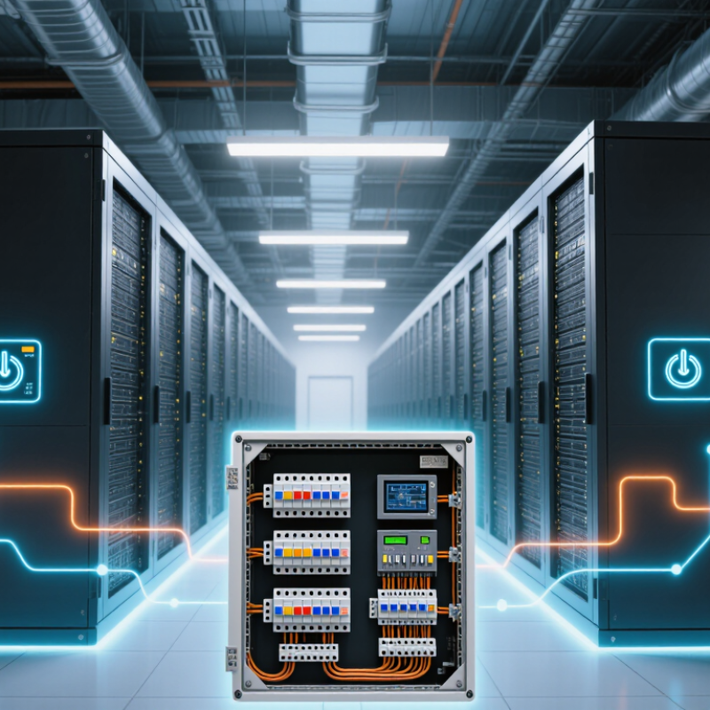
A PDU switchboard is a controlled power distribution cabinet for data centers, industrial rooms, and critical facilities. It receives electricity from an upstream source and divides it into protected branch circuits. Inside, busbars, circuit breakers, meters, and cable terminals work together. The system sends stable power to racks, machinery, or other loads. Some models also include automatic transfer functions, remote monitoring, and environmental sensors.
Its operation is straightforward, but not simple. Incoming power enters the main isolator or breaker. Current then travels through busbars to individual outgoing breakers. Each breaker limits fault energy and allows technicians to isolate one circuit. Digital meters can display voltage, current, frequency, and energy use. In a three-phase system, balanced loading matters. An overloaded phase can create heat, nuisance trips, and wasted capacity.
Choose a switchboard by checking the real load, future expansion, fault rating, enclosure protection, and maintenance access. Leave usable space for additional breakers and cables. Ask for factory test records, wiring diagrams, thermal checks, and compliance documentation from qualified personnel. Monitoring is valuable, but sensors need calibration and clear alarm settings. Field inspections often find poor labels or crowded terminals. Small details matter. A beautifully designed cabinet can still fail when installation records are incomplete or operators misunderstand the alarms.
How to Choose a PDU Switchboard in 2026?
A PDU switchboard must match the site’s voltage, frequency, phase, and available fault current. Confirm these values from the electrical design, not from an old equipment label. The board should support the calculated continuous load with practical spare capacity. A common planning mistake is treating maximum rated current as normal operating capacity. Apply the margin required by local electrical codes and the project engineer’s load study. Measure twice.
Each feeder needs suitable overcurrent protection, short-circuit withstand capability, and clear isolation. Check breaker coordination so a downstream fault does not shut down an entire rack row. Copper or aluminum busbars must handle heat without excessive temperature rise. Grounding and bonding require particular attention, especially where sensitive servers share power paths. Keep it serviceable. Leave enough working space for testing, cable routing, and future circuit additions.
Monitoring should show voltage, current, power factor, energy use, and alarm conditions at useful intervals. For critical facilities, consider dual inputs, bypass arrangements, and maintainable sections without unnecessary shutdowns. Enclosure protection must suit the room’s dust, moisture, and cooling conditions. Certification should align with applicable regional standards and inspection requirements. I would also question every “future-ready” claim. Extra capacity is valuable only when the busbar, breakers, terminals, and cooling system can support it. A site acceptance test should verify torque, phase sequence, insulation, alarms, and load behavior under realistic conditions.
Typical nominal power capacity by PDU switchboard configuration
The values are calculated from common IEC-rated supply configurations: single-phase 230 V and three-phase 400 V. Nominal apparent power is calculated as voltage × current for single-phase systems and √3 × voltage × current for three-phase systems. Actual usable capacity should be lower to allow for continuous-load limits, redundancy, ambient temperature, voltage drop, protection coordination, and future expansion.
Choosing a PDU switchboard in 2026 starts with comparing architecture, not cabinet appearance. Rack-mounted PDUs suit smaller zones and provide outlet-level monitoring. Floor-mounted units support higher capacity, larger breakers, and easier maintenance access. For critical rooms, compare single-input, dual-input, and bypass configurations. A dual-corded server needs independent A and B power paths. One path is not redundancy.
The International Energy Agency’s Energy and AI report estimates data-center electricity use could rise from about 415 TWh in 2024 to 945 TWh by 2030. That growth makes thermal limits and future capacity important. Choose three-phase distribution when loads justify it, but confirm voltage, fault ratings, neutral sizing, and available short-circuit current with a qualified engineer. Small details matter. A wrong neutral assumption can create heat.
Uptime Institute’s Annual Outage Analysis reports that power problems remain a leading cause of serious data-center outages. Therefore, compare breaker selectivity, maintenance bypasses, surge protection, metering accuracy, and alarm integration. Static transfer switching can improve resilience, but it adds cost and another failure point. I would not accept “high availability” without reviewing test records, maintenance procedures, and transfer performance. Forecasts are uncertain. Leave practical expansion space, yet avoid buying oversized equipment that operates inefficiently at light loads.
| PDU Type | Primary Function | Typical Input Configuration | Typical Output Configuration | Monitoring and Control | Common Current Range | Best-Fit Application | Main Advantages | Key Limitations |
|---|---|---|---|---|---|---|---|---|
| Basic PDU | Distributes power to connected equipment without local metering or remote communication. | 120 V single-phase 208–240 V single-phase 208 V three-phase | IEC 60320 appliance outlets, locking outlets, or facility-specific receptacles; outlet count commonly ranges from 8 to 42. | No built-in electrical measurement or outlet switching. | 10–60 A, depending on voltage, connector, and installation method. | Small server rooms, network cabinets, laboratory racks, and non-critical equipment. | Lowest purchase cost, simple operation, and fewer electronic components. | Provides little information about load growth, imbalance, or circuit capacity. |
| Metered-Input PDU | Displays the total electrical load at the PDU input. | Single-phase Three-phase Local display | Fixed outlet arrangement selected for the rack voltage and plug type. | Local measurement of voltage, current, power, power factor, and accumulated energy; remote access is normally unavailable. | 16–63 A is common for rack-level units. | Facilities that need local capacity checks but do not require centralized monitoring. | Helps prevent accidental circuit overloading and supports on-site troubleshooting. | Does not normally provide outlet-level data or remote alarms. |
| Monitored PDU | Measures electrical conditions and sends operating data to a management platform. | Single-phase Three-phase Network-enabled | Fixed or mixed outlet groups; outlet-level measurement may be available on advanced configurations. | Remote voltage, current, power, energy, power factor, phase load, thresholds, alarms, and historical data. | 16–63 A is common; higher ratings require coordinated facility protection and cabling. | Medium and large data centers, colocation rooms, and sites with capacity-management requirements. | Improves visibility, capacity planning, alerting, and energy reporting. | Higher cost and requires network connectivity, configuration, and cybersecurity controls. |
| Switched PDU | Provides remote control of individual outlets or outlet groups in addition to monitoring. | Single-phase Three-phase Network-enabled | Controlled outlet banks or individual outlets; outlet sequencing may be supported. | Remote outlet on/off, delayed reboot, outlet current measurement, user permissions, alarms, and event logs. | 16–63 A is common for rack-mounted units. | Remote sites, high-density racks, lights-out facilities, and equipment requiring controlled reboot. | Reduces on-site service visits and supports orderly equipment startup and shutdown. | Incorrect switching can interrupt equipment; access control and fail-safe procedures are essential. |
| Automatic Transfer PDU | Transfers a connected load between two independent power sources when the preferred source fails. | Dual input Same nominal voltage Source monitoring | Usually single-phase rack outlets; output capacity is limited by the PDU rating and source availability. | Source status, input voltage, current, transfer events, alarms, and optional remote communication. | Commonly 16–60 A for rack-level applications. | Single-cord equipment supplied by two separately protected upstream power paths. | Improves availability when one upstream source is lost or removed for maintenance. | Both sources must be compatible; it does not replace a UPS and does not provide battery backup. |
| High-Density Three-Phase PDU | Distributes higher power through multiple phases for dense computing or industrial loads. | 208/120 V three-phase 400/230 V three-phase Wye or equivalent system | Combination of single-phase and three-phase outlets selected according to the connected equipment. | May include per-phase, circuit-level, or outlet-level monitoring and phase-balance alarms. | Commonly 16–63 A at rack level; facility switchboards can be rated substantially higher. | High-density computing racks, industrial control cabinets, and large equipment enclosures. | Higher power capacity, better conductor utilization, and improved phase-load management. | Requires qualified installation, correct phase identification, and careful load balancing. |
| Busway-Mounted PDU Tap-Off | Obtains power from an overhead or underfloor busway and distributes it locally to a rack or equipment row. | Plug-in tap-off Single or three-phase Busway compatible | Usually feeds a rack PDU, distribution panel, or row-level power assembly. | Depends on the connected PDU; optional metering can be installed at the tap-off or downstream device. | Determined by the busway tap-off rating, commonly 16–125 A in modular distribution systems. | Data halls requiring flexible rack deployment and frequent cabinet moves or additions. | Supports modular expansion and can reduce fixed cabling changes during layout revisions. | Must match the busway system, protection coordination, short-circuit rating, and installation rules. |
In 2026, choosing a PDU switchboard means checking protection, visibility, and control together. Uptime Institute’s 2024 Global Data Center Survey reports that 53% of respondents experienced an outage within three years. Power remains a frequent trigger.
A practical design starts with correctly rated breakers, short-circuit withstand capacity, and selective coordination. These features help isolate a failed branch without darkening an entire rack row. Ask for tested thermal performance, clear labeling, and maintenance access. A tidy cabinet is not automatically a safe cabinet.
Monitoring should show more than total amperage. Measure voltage, current, power factor, energy, frequency, and temperature at incoming and branch levels.
The International Energy Agency reports that data centers consumed about 460 TWh globally in 2022, with demand potentially exceeding 1,000 TWh by 2026.
That growth makes poor load visibility expensive. Set thresholds for overload, phase imbalance, hot connections, and rapid temperature rise. Alerts should reach the right technician, not everyone. Use timestamps and retained event logs.
Remote management needs role-based access, encrypted communications, two-factor authentication, and firmware controls. Integrate the PDU with DCIM or building systems through documented APIs.
The 2023 Ponemon Institute study estimated the average cost of a data-center outage at about 740,357 dollars. That figure is useful, but it can hide smaller operational losses.
I would test alarm accuracy under a simulated fault, then review the result with electricians. A dashboard can still lie. Poor sensors, stale firmware, or an ignored alert can defeat excellent hardware. Require independent test records and a clear replacement plan.
Choosing a PDU switchboard begins with the real load, not the cabinet’s appearance. Record voltage, phase arrangement, connected load, starting current, and expected expansion. Size busbars and breakers for continuous demand, short-circuit capacity, and available fault current. Leave spare ways for future circuits. Crowded boards make servicing harder. Select an enclosure suitable for dust, moisture, heat, and cleaning conditions. Decide whether metering, remote alarms, or automatic transfer is truly necessary. Extra features can create additional failure points.
Installation should be completed by qualified electrical personnel under approved site procedures. Verify isolation before work begins. Check cable bend radius, phase sequence, neutral separation, protective earthing, and clear circuit labels. Use a calibrated torque tool on terminals, following the specified values. A loose connection may remain invisible until it produces heat, odor, or an unexpected shutdown. Commissioning should include insulation checks, protective-device settings, alarm verification, and a controlled load test. A thermal scan after normal loading can reveal weak connections.
Maintenance needs a schedule based on operating hours, dust levels, humidity, and system importance. Inspect for discoloration, unusual noise, damaged insulation, and blocked ventilation. Review energy readings and alarm records for changing patterns. Clean only with approved methods and de-energize equipment before internal work. Retorque connections only when procedures permit. Some uncertainty remains. No specification predicts every site condition, so maintenance records should challenge the original design rather than simply confirm it.
© 2025 Messer Cutting Systems, Inc.