© 2025 Messer Cutting Systems, Inc.

Choosing the right capacitor begins with understanding how electrical charge behaves in real circuits. Capacitors And Capacitance are closely related, but they are not identical terms. Capacitance describes a component’s ability to store charge. A capacitor is the physical device that provides this function.
Different capacitor types suit different working conditions. Ceramic capacitors respond quickly and often support high-frequency filtering. Aluminum electrolytic capacitors offer substantial capacitance in a compact, affordable package. Film capacitors provide stable performance, low losses, and strong reliability in timing or power applications. Tantalum capacitors can deliver excellent volumetric efficiency, but they require careful voltage and current control.
Small details matter. A 10-microfarad capacitor may look harmless on a workbench, yet its voltage rating, polarity, temperature range, and equivalent series resistance can change circuit performance. In practical testing, a capacitor that measures correctly at room temperature may behave differently near its rated limits. That is easy to overlook.
This guide explains major capacitor families, capacitance values, dielectric materials, and common selection mistakes. It also examines tolerance, leakage current, ripple current, and frequency response. These specifications are not merely catalog numbers. They influence noise levels, startup behavior, signal accuracy, and service life.
Some recommendations remain application-dependent. No single capacitor type is universally best. Engineers should verify manufacturer data, measure critical circuits, and allow suitable safety margins. That habit builds trust. Mistakes still happen, especially when designers focus only on capacitance. A broader evaluation usually produces a safer, more dependable result.
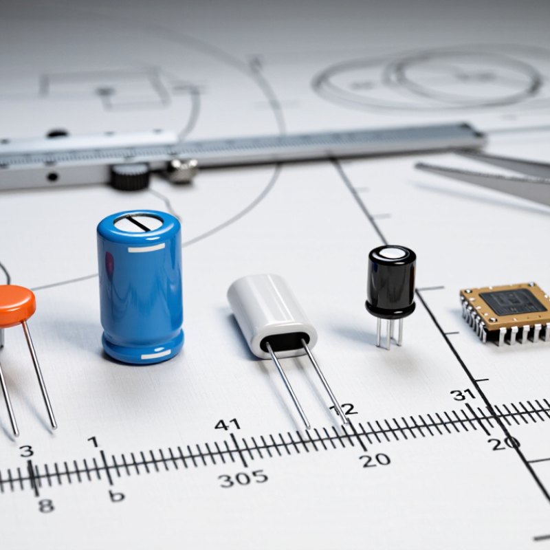
Top Capacitors and Capacitance Types Explained
Capacitance describes how much electrical charge a capacitor can hold for each volt applied. It is measured in farads, although microfarads, nanofarads, and picofarads are more common. A capacitor stores energy in an electric field between two conductive plates. The dielectric material separates those plates and influences performance. Energy follows the formula E = ½CV², so voltage affects stored energy strongly. A small capacitor can still become important in a high-voltage circuit.
Different capacitor types suit different tasks. Ceramic capacitors respond quickly and work well for filtering noise. Electrolytic capacitors offer higher capacitance in compact sizes, but their polarity must be respected. Film capacitors usually provide stable values and low signal distortion. Supercapacitors store much more energy, though they behave differently from batteries. In practice, temperature, leakage, tolerance, and aging can change the expected result. Real measurements are less tidy. I have found that a printed value is only a starting point.
Tips: Check voltage ratings with a safe margin. Never reverse a polarized capacitor. Measure capacitance after disconnecting power and discharging the component. Keep leads short when reducing high-frequency noise. Remember that capacitance alone does not define quality; equivalent series resistance and operating temperature matter too. A careful design leaves room for error.
Capacitors store electrical energy and release it when circuits demand quick support. Their behavior depends on capacitance, voltage rating, frequency, temperature, and internal losses. According to Mordor Intelligence’s 2024 capacitor market report, demand is projected to grow steadily through 2029, driven by electric vehicles, renewable systems, and industrial electronics.
The figure matters, but application details matter more.
Ceramic capacitors offer low equivalent series resistance and strong high-frequency performance. They suit noise filtering near processors and switching circuits. However, their capacitance can fall under direct-current bias, which engineers sometimes underestimate.
Aluminum electrolytic capacitors provide high capacitance at relatively low cost. They support power-supply smoothing, but heat and ripple current shorten their service life.
Tantalum types deliver stable capacitance in compact packages, although voltage derating remains essential.
Film capacitors provide low loss, long life, and reliable pulse handling. They are useful in inverters, filters, and motor circuits, but usually require more board space.
Supercapacitors store far more energy than conventional capacitors and handle frequent charge cycles. Their voltage per cell is low, so systems often require series connections and balancing.
The International Energy Agency’s Global EV Outlook 2024 reports that electric car sales exceeded 17 million in 2024 estimates, increasing demand for reliable power electronics.
Real testing still matters. A catalog value is not a field result. Engineers should measure temperature rise, ripple current, aging, and transient response under actual operating conditions.
Ceramic, electrolytic, film, and tantalum capacitors can all store electrical energy, but their behavior differs in real circuits. Ceramic capacitors are compact, fast, and effective at filtering high-frequency noise. Their capacitance can change with voltage, especially in smaller packages. Electrolytic capacitors provide high capacitance at a low cost, making them useful for power supply smoothing. They are polarized, so reversed installation can cause failure.
Film capacitors offer stable capacitance, low losses, and strong performance in timing, audio, and pulse applications. They usually need more board space. Tantalum capacitors are small and provide steady capacitance, but they require careful voltage derating and current control. In my repair experience, ignoring surge conditions caused more problems than choosing the wrong capacitance value. That detail is easy to miss.
Tips: Check capacitance, voltage rating, tolerance, temperature range, and polarity before installation. Leave safety margin above the circuit’s normal voltage. Measure suspicious parts in-circuit only when other components cannot distort the reading. A capacitor may look perfect outside. Inspect leakage current, equivalent series resistance, and physical swelling when reliability matters. I also compare the datasheet’s ripple rating with the circuit’s actual load. This step takes time, but skipping it can produce unstable performance.
A practical comparison of common capacitor technologies, electrical characteristics, strengths, limitations, and typical applications.
| Capacitor Type | Dielectric / Construction | Typical Capacitance Range | Common Voltage Range | Polarity | Typical Tolerance | Frequency Behavior / ESR | Temperature Characteristics | Key Advantages | Main Limitations | Typical Applications |
|---|---|---|---|---|---|---|---|---|---|---|
| Ceramic | Ceramic dielectric, commonly multilayer ceramic construction. Class 1 types offer high stability; Class 2 types provide higher capacitance per volume. | About 1 pF to 100 µF, depending on dielectric class, package size, and voltage rating. | Approximately 6.3 V to 5 kV or higher for specialized parts. | Non-polarized | About ±0.05% to ±20%; ±5% and ±10% are common. | Very low ESR and excellent high-frequency performance. Class 2 capacitance can change with DC bias, temperature, and aging. | Class 1: highly stable. Class 2: commonly rated around −55°C to +125°C, with capacitance variation depending on dielectric code. | Small size, low loss, low ESR, strong high-frequency filtering, and long service life. | Large-value parts may lose capacitance under DC bias; brittle bodies can crack under mechanical stress; some devices can be acoustically active. | Decoupling, bypassing, RF circuits, resonant networks, timing, signal filtering, and voltage stabilization. |
| Electrolytic | Anodized aluminum or similar valve-metal electrode with a liquid, polymer, or hybrid electrolyte. | About 0.1 µF to 100,000 µF; very large values are widely available. | Approximately 6.3 V to 700 V, with higher-voltage specialty designs available. | Usually polarized; bipolar versions exist for selected AC applications. | Typically ±20%; tighter tolerances are available but less common. | Higher ESR and leakage than ceramic or film types. Performance generally declines as frequency increases. | Commonly −40°C to +105°C or +125°C. Useful life depends strongly on temperature, ripple current, and operating conditions. | Very high capacitance, good energy storage, cost-effective bulk filtering, and strong ripple-current options. | Polarity must be observed; finite service life; comparatively high leakage, ESR, size, and tolerance. | Power-supply smoothing, DC-link filtering, bulk decoupling, audio equipment, and energy buffering. |
| Film | Plastic film dielectric such as polypropylene or polyester, using wound or stacked metalized-film construction. | Approximately 10 pF to 100 µF; high-capacitance power-film parts may be physically large. | About 16 V to 30 kV, depending on construction and application. | Non-polarized | Commonly ±1%, ±2%, ±5%, or ±10%. | Low ESR and low dielectric loss, with stable behavior over frequency. Suitable for high pulse currents in appropriate designs. | Often rated around −40°C to +85°C, +105°C, or +125°C; generally exhibits low aging and good stability. | Excellent stability, low loss, high pulse capability, self-healing in many metalized designs, and no polarity requirement. | Larger physical size, lower capacitance density, and often higher cost than ceramic or electrolytic alternatives. | AC filtering, snubbers, timing, audio signal paths, motor-run circuits, resonant converters, and power-factor correction. |
| Tantalum | Porous tantalum anode with a tantalum-oxide dielectric and solid manganese-dioxide or conductive-polymer cathode system. | Approximately 0.1 µF to 1,000 µF, with many practical values in the 1 µF to 470 µF range. | Typically 2.5 V to 100 V; higher-voltage parts are less common. | Polarized; reverse voltage must be avoided. | Commonly ±10% or ±20%; tighter tolerances are available. | Lower ESR than many conventional electrolytics, particularly for polymer types, but ESR and ripple capability vary significantly by construction. | Often rated around −55°C to +125°C. Capacitance and reliability depend on temperature, applied voltage, ripple, and surge conditions. | High capacitance density, compact size, stable capacitance, and useful low-ESR options. | Sensitive to reverse voltage, surge current, and overvoltage; failure can be abrupt if derating and protection are inadequate. | Portable electronics, compact power rails, processor decoupling, telecommunications equipment, and space-constrained circuits. |
Choosing a capacitor starts with voltage, frequency, and application, not capacitance alone. A 2024 MarketsandMarkets report estimates the global capacitor market will grow steadily through 2029, driven by electric vehicles, renewable energy, and data equipment. That growth reflects a practical issue: each circuit demands a different electrical compromise.
Ceramic capacitors suit high-frequency noise suppression because their low equivalent series resistance supports fast switching. Aluminum electrolytic capacitors provide high capacitance for power smoothing, but their temperature and ripple-current limits need careful checking. Film capacitors offer stable performance in filters and pulse circuits. They are larger, though.
Voltage rating needs headroom. I usually allow at least 20% above the measured peak voltage, then review transients and temperature. That is not a universal rule. Standards such as IEC 60384-1 require defined electrical and safety tests, while IEEE Std 18-2022 addresses capacitors used in power systems.
At high frequency, self-resonance can matter more than the printed capacitance. A 10 μF part may perform poorly where a smaller 100 nF part works better. This detail is easy to miss.
Tips: Check DC bias for ceramic capacitors, because effective capacitance can fall sharply. Compare ripple current at the real operating temperature. For AC power applications, verify insulation, discharge behavior, and harmonic stress. Read the complete datasheet, not only the headline value. I have seen designs pass bench testing, then fail after heat exposure. Recheck assumptions before production.
Capacitor markings can look cryptic, but each symbol carries practical information. A code such as 104 means 10 followed by four zeros in picofarads, or 100 nF. Values may also appear directly, such as 47 µF. Check the unit carefully; confusing nF with µF can change circuit behavior dramatically. The voltage rating is the maximum safe working voltage, not the expected operating voltage. Choose a component with comfortable voltage headroom.
Tolerance describes how far the actual capacitance may differ from its printed value. A 100 µF capacitor rated at ±20% may measure between 80 and 120 µF. Temperature, aging, frequency, and ripple current can shift that reading. Ceramic capacitors often lose capacitance under applied voltage. That detail is easy to miss. It deserves attention in timing and filtering circuits.
Polarity requires equal care. Electrolytic capacitors usually mark the negative side with a stripe, while the shorter lead may indicate negative polarity. Install the positive lead toward the higher potential. Reversing it can cause heating, leakage, or rupture. Non-polarized capacitors, including many ceramic types, do not require directional placement. Before handling a larger capacitor, disconnect power and verify discharge with a suitable meter. In bench work, a quick visual check helps: swelling, leaking, or a lifted vent signals replacement. I once trusted a printed value without checking the meter, and the circuit behaved poorly. Measurements should confirm markings, not merely repeat them.
© 2025 Messer Cutting Systems, Inc.